Mechanical & Engineering Drawings
Background:
The C&O’s Engineering Department was first headquartered in the railway’s main offices in the First National Bank Building in Richmond, VA until about 1960. About that time, the engineering office was transferred to Huntington, WV and installed in the Operating Headquarters Building (O.H. Building) which was an obsolete General Electric factory building that the railway had purchased. During the move, the drawing files were purged and many obsolete drawings were destroyed. After the move, periodically, obsolete drawings were destroyed as well. Other drawings that pertained to structures were transferred in the 1960’s to the newly created Architect’s Office. When the C&OHS visited the O.H. Building, this office was also visited; but, only a portion of the structure drawings were allowed to be removed.
Chief Engineer Drawings:
This collection contains drawings made by the C&O’s Engineering Department for use in construction, building, demolition, and modification of track, roadway, buildings, and other facilities. Also included are surveys, profiles, and geographical maps showing general scenes over large and small areas, some showing only the general lay of the lines and others showing more detail such as track curvature and land and building features. The collection has a number of sub-sets of drawings, most designated by a prefix letter as described below. The main collection is numbered sequentially and chronologically with the earliest numbers beginning apparently about 1880. The series carries through, unbroken, to the 1980’s. Drawing numbers were also sometimes assigned to prints of drawings from other railroads or companies with the original company’s drawing number or designation sometimes obliterated and sometimes not. Drawing numbers were also applied to commercially printed maps and drawings, especially city maps and plats.
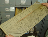
The media type for most of the original drawings is ink drawn on starched and treated linen cloth, which is translucent so that the drawing could be reproduced using a chemically treated paper and an ammonia or “diazo” printing process. This process created a blueprint (white line-work on a dark blue background) or a blueline (dark blue line-work on a white background) duplicate. Other media types, in much smaller quantities are: pencil or ink on onion skin paper, pencil or ink on vellum paper, pencil or ink on mylar (translucent plastic film, post 1970), and pencil or ink on regular paper. Sometimes, copies or reproducible masters of an original drawing were made by copying the original drawing onto brown translucent film called sepia or Van Dyke paper (1920’s-1960’s), which could then be used to make additional blueprint copies.
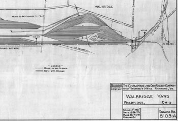
Drawings were made using a variety of drafting standards which changed down through the years. Drawing scales are of two types: Architectural scale, in which a fraction of an inch is equal to one foot (i.e. 1/8″ = 1′-0″, 1/4″ = 1′-0″, 3/16″ = 1′-0″); or Engineering scale, in which one inch equals ten feet or more, usually expressed in even ten-foot increments (i.e. 1″ = 30′, 1″ = 50′, 1″ = 100′). Generally speaking, the architectural scales were used on drawings related to building construction and the engineering scales were used on drawings that related to civil work such as track maps and land surveys. Drawings usually have a Title Block, but not always. The use of a standard title block in the lower right-hand corner of drawings was begun in the World War I era and is almost uniformly applied from that point until the end of the series. This title block gives the name of the railway, division and sub-division, county and state, station name, date originally drawn, initials of the person preparing the data, the initials of the person drafting the drawing, initials of the person checking the drawing, the Valuation Section of the railway, a space for revision dates, and the drawing number. Prior to World War I, no standard title block was used. The title could be placed at the top center or in any corner of the drawing. In some cases the drawing number was apparently entered later. Sometimes a rubber stamp data block was used, usually in the lower right corner that has just the railway’s name and “Chief Engineer’s Office.” Some of the drawings before the era of standardized title blocks are not dated, but this comprises only a few.
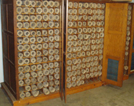
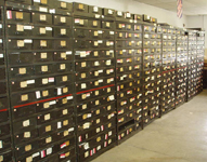
In the distant past, drawings were prepared directly by the Chief Engineer’s Office and sometimes the Engineer, Maintenance of Way’s Office. In the more modern era, starting in the 1920’s and lasting through the Chessie System era, a subordinate office of the Chief Engineer was responsible for preparing the drawings. This official was called the Office Engineer and he and his staff comprised the “Office Engineer’s Office”. This is the location where the engineers and draftsman worked , from which field forces were dispatched, and to which their notes and data were returned. The office also maintained the file copies of all original drawings and engineering data and had them reproduced and sent on demand to the locations where they were needed. The drawings were housed in a series of large metal drawers along one wall of the Office Engineer’s Office which was called “The Great Wall”. In connection with the Office Engineer’s drawing filing system, a card index file was maintained onto which an entry was made for each new drawing that was created. The cards list drawings for the main series and for the sub-sets with letter prefixes. The cards were filed alphabetically by station name. Entries were made as the drawings were prepared and are thus in chronological order. A second set of cards listed the drawings in numerical order and a third set of cards were organized by selected subject, such as: engine terminals, coaling stations, freight stations, etc.
Within the overall group of Chief Engineer’s Drawings, there are sub-sets of drawings designated with a letter prefix. These letter prefixes are indicated on the drawings themselves and on the index cards. The following list shows the various letter prefixes used and a brief description of each type of drawing and its use:
- BL – This collection contains drawings prepared by the “Engineer of Branch Lines” which was apparently an office created in the early 20th century during the time that so many branch lines were being constructed to tap into the many coal lands. The series runs from about 1902 to about 1920 and consists mostly of ink on linen drawings of various sizes. Some drawings also show some mainline facilities.
- CE – This collection contains drawings that are very similar in subject matter to the “X” Series. We have a few hundred of these drawings which are all 8 1/2″x11″. The reason for the “C.E.” prefix is unknown; but, may have stood simply for Chief Engineer.
- MW – This collection contains drawings that were prepared by the “Engineer, Maintenance of Way”, which was another sub-office of the Chief Engineer’s Office. These drawings supplemented and eventually replace the “S” series Standard Drawings. Most of these drawings are track and roadway standards, such as: turnouts, ballast profiles, track construction details, etc. Many are 5″x14″ or slightly shorter or longer so as to fit in Standards Books which were supplied to Division officials and engineering personnel all across the system. The collection also includes drawings that show roadway improvements, surveys, diagrams of accidents, and a variety of other subjects which could just have easily appeared in the Office Engineer’s main set of drawings. The C&OHS has a very incomplete set of these drawings with the majority being blueprints for use in the Standards Books. Only a few are the original ink on linen plans.
- R – This collection contains Joint-Standards drawings for all Van Sweringen affiliated railroads (C&O, Erie, NKP, PM). They are Maintenance of Way Standards and all are blueprint copies which were made for the Standards Books.
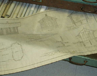
- S – This collection contains various Standard Drawings that range from standard station buildings and other structures, hardware, furniture, tools and implements, etc. They are of various sizes but generally are not larger than 24″x36″ and are almost all ink on linen drawings. The practice of using this set of standards seems to have been discontinued in the 1920’s and most standards thereafter were drawn by the Maintenance of Way Department and were contained in their number series as noted above.
- SD – This collection contains standard drawings for the Signal Department which had its own draftsmen. They are standards for signal facilities of all types and are generally small so they can be used in Signal Standards Books which were supplied to maintainers and supervisors, etc. The C&OHS has only a few of theses drawings.
- V – This designation, which is only shown on the index cards, referred to a “Vault Number” which told the Office Engineer’s personnel that a particular drawing was not located in The Great Wall. This prefix referred to a specific storage area where odd sized or over-sized drawings were stored. Many very large and long survey drawings are part of this collection. Also contained in this collection are drawings from other railroads, early independent lines that were merged into the C&O, commercial drawings, drawings from contractors who built C&O facilities, large maps, etc. Other items in this collection included commercial atlases and other similar publications.
- WS – This collection contains drawings prepared by the Water Service Department which had its own draftsmen. These drawings are of standard water facilities, piping, details, etc. and other drawings for particular locations necessary to facilitate construction, installation, maintenance, and use of the water facilities, including pipes, pumps, tanks, etc. The C&OHS has only a few of these drawings.
- X – This collection contains drawings that were generally small and could be filed flat in an ordinary letter-sized file folder. Almost all of these are 8 1/2″x11″ or 8″x10″ size. They are mostly ink on linen; but, perhaps 10% of them are estimating forms used to prepare costs for the installation of side tracks or industrial spurs. These pages have a small plat drawing at the top and the bulk of the form consisting of cost and material estimates. These are on onion skin paper so as to be reproduced by the diazo process and are very delicate.
Hard Maps:
The Hard Map drawings were prepared using data and notes gathered from the engineering and surveying personnel working out in the field.
Regular engineering drawings, primarily the Valuation Maps, were made using the hard map as a starting point and tracing over them. Hard Maps are drawn with both ink and pencil on thick linen which is backed with a stiff paper which creates a very thick substance, thus the name. These are not translucent and cannot be reproduced using the old blueprint or diazo method.
The C&OHS began acquiring drawings from the Office Engineer in 1982. At that time, representatives from the C&OHS would spend one or two days at the O.H. Building in Huntington, WV where a representative of the Office Engineer would help us go through the drawings drawer by drawer and he would identify which drawings he considered surplus. These drawings would be given to the C&OHS and the ones he wanted to retain were put back in the drawers. This process went on for about four years whenever a C&OHS representative could make the trip. The C&OHS representatives were often Thomas W. Dixon, Jr. and J. Randolph Kean, supplemented on occasion by various other C&OHS members.
By this time, 1986-87, CSX had made the decision to consolidate all of the engineering operations in Jacksonville, FL and close the O.H. Building in Huntington, WV. Then president of CSX, Ron Drucker, agreed that the engineering department personnel would leave in the O.H. Building anything they didn’t want to move to Jacksonville. At a pre-arranged time, a team of C&OHS volunteers arrived and removed from the building all the materials that had been left. This material was place into two boxcars, which were also donated to the C&OHS, and moved to the C&OHS Headquarters in Clifton Forge, VA. The material from one of these cars formed the basis for the initial collections in the C&OHS Archives Building at 312 E. Ridgeway St. in Clifton Forge, VA in 1987.
Hinton Division “As Built” Engineering Drawings:
This is a small, special collection of drawings related only to the Hinton Division of the C&O and comprises only “As-Built” plans. “As-Built” means just that, these plans show what was actually built, which makes them an exceptionally valuable resource. These plans are blueprint copies of regular Chief Engineer’s Drawings. Most, if not all, of these plans are included somewhere in that collection; however, this special series of blueprint copies have been organized and kept separate because there is a great deal of interest in this particular Division of the C&O. These drawings are completely indexed and cataloged on paper, but are not in the online Drawing Database.
Chicago Division Engineering Drawings:
This is a special collection of engineering drawings related only to the Chicago Division of the C&O. These include plans labeled: C&O; C&O of Indiana; Chicago, Cincinnati & Louisville; Cincinnati, Richmond & Muncie; Chicago & Cincinnati; and Cincinnati & Indiana Western; all of which were predecessors of the C&O and were merged into the C&O in 1910 to become the C&O’s Chicago Division. This collection also includes plans that were developed by the C&O’s Division Engineer’s Office in Peru, IN. These plans are drawn on a variety of media including: linen, vellum, sepia, blueprint, onion skin paper, and regular paper. Most of these plans are not included in the larger collection of C&O Chief Engineer’s Drawings. These drawings are designated in the C&OHS Drawing Database by the “Collection” notation: “COI” (for C&O of Indiana.) These drawings are partially indexed in the computer Drawing Database and are partially cataloged.
Hocking Valley Railway Engineering Drawings:

This is a special collection of engineering drawings that relate only to the Hocking Valley Railway which was merged into the C&O in 1930. These drawings were prepared by the Hocking Valley Railway’s engineering department in Columbus, OH. This office was later merged into the C&O’s engineering department in Richmond, VA and the engineering drawings were also moved to Richmond intact. When the C&OHS began to remove surplus drawings from the C&O’s files in the early 1980’s, the HV files were in drawers marked “HV”. It was apparent that the C&O made no attempt to integrate these drawings into the main set of drawing files and they did not assign new numbers to these drawings. The C&OHS has maintained the collection in this same manner. The drawings have one or two letter prefixes followed by numbers. It is thought that the letter prefix was to indicate a specific drawer or drawer size in which the drawing was stored when it was created in the 1900-1930 era. It should be noted that the main C&O drawing files contain little in the way of plans from areas of Ohio. It appears that if the C&O Office Engineers needed to draw plans for anything in Ohio, they simply used the Hocking Valley drawings as a source to create their new drawings. The Hocking Valley plans are drawn on a variety of media including: linen, vellum, sepia, blueprint, onion skin paper, and regular paper. Most of these plans are not included in the larger collection of C&O Chief Engineer’s Drawings. These drawings are designated in the C&OHS Drawing Database by the “Collection” notation: “HV” (for Hocking Valley.) There is no card index file for these drawings, but the drawings have been fully indexed in the online Drawing Database and are completely cataloged.
Mechanical Engineering Drawings:
This is a vast collection of mechanical drawings that detail nearly every aspect of the C&O’s diesel locomotives, passenger cars, and freight cars. This collection includes: car diagrams, general arrangement drawings, and painting and lettering diagrams, for nearly every piece of rolling stock that the railroad owned. All of the drawings are organized using a numbering system developed by the C&O’s Mechanical Department. These drawings are partially indexed in the online Drawing Database and there is a card file index for the freight car portion of the collection. Some of the painting and lettering diagrams are cataloged in Hollinger Boxes.
Steam Locomotive and Tender Erection Drawings:

This is a collection of Mechanical Drawings that detail the design of the various parts of several of the C&O’s classes of steam locomotives and tenders and contains construction, or erection, drawings showing how all of the parts are assembled. All of the plans are drawn in ink on linen or are blueprint copies. These drawings are designated in the C&OHS Drawing Database by the “Collection” notation: “LED” (for Locomotive Erection Drawing.) These drawings are fully indexed in the online Drawing Database and are completely cataloged.
Bridge Engineering Drawings:
This is a special collection of engineering drawings detailing various bridges all along the C&O system. These drawings are partially organized and indexed on paper; but are not yet in the computer Drawing Database. There is also a partial card file index for these drawings.